TAO
TAO TRUMP
TRUMP XRP
XRP TONCOIN
 SOL
SOL ETH
ETH BTC
BTC ANSEM
ANSEM ATTN
ATTN WLFI
WLFI RICH
RICH DEV3
DEV3


Thermal conductivity guide for FR4 circuit boards

FR4 Thermal Conductivity administration for LEDs
Much like the light-emitting diode, which for years offered solely as an indicator lamp, PCB has likewise left its shadowy presence as well as has quickly progressed to a multifunctional element within an electronic system. It, for that reason, has to withstand high currents and guarantee the air conditioning of high-clocked, yet heat-producing CPUs as well as heat-dissipating power parts, which brought us to today’s topic- FR4 thermal conductivity.
1. The contrast of a conventional two-board remedy with FR4/ copper mix
As UHB LEDs (Ultra High Brightness LEDs) with as much as 10 or more watts per real estate and also LED varieties with numerous LEDs placed closely next to each other are being made use of increasingly more, the inquiry of warmth dissipation is coming to be an increasing number of press.
This uses specifically given that, unlike incandescent lights, light-emitting diodes just emit a negligible part of the heat loss; virtually everything goes the means of warmth transmission.
Of course, there are solutions, for instance, ceramic carriers or IMS PCB (protected steel substrates) with thick lightweight aluminum cores. Nevertheless, these are costly in comparison to classic FR4 PCB boards, and also a 2nd board is typically needed to make to accommodate motorist electronics.
FR4 PCB with copper cord
Moko Technology takes various methods with “HSMtec”. The technology, which is qualified based on DINEN60068-2-14 and JEDECA101-An and also audited for aeronautics and automobile, is careful: only where high currents are supposed to stream via the printed circuit board does thick copper.
Currently, 500µm high profiles with widths from 2.0 mm to 12mm are available in variable lengths, with cables a diameter of 500µm has come to be established. The solid copper components that are securely bonded to the conductor patterns can be used directly to the base copper using ultrasound connection technology and integrated into any kind of layer of a multilayer making use of FR4 base material. There are several reasons why copper is made use of: It has two times the thermal conductivity contrasted to lightweight aluminum and thus makes sure rapid warm dissipation without protecting intermediate layers underneath the LED warmth pad.
Table 1: Thermal conductivity of the products entailed
One more benefit of copper and the motherboard base product FR4 is the thermal development homes (Table 2): Especially about ceramic LEDs, circuit boards based upon copper or FR4 have a high resistance to thermal stress and anxieties, which depend upon environmental or operating problems as well as others Temperature level cycles, such as for “intelligent” lights controls.
Table 2: Thermal expansion coefficient in the X/ Y instructions
In this way, the lifespan as well as reliability of the entire lights device can be considerably increased contrasted to conventional metal core PCB based on aluminum.
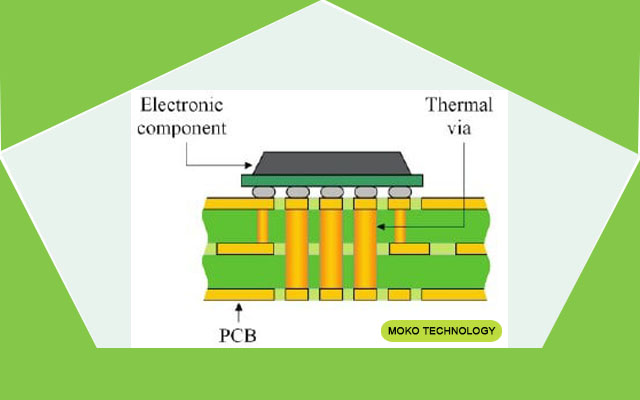
Printed circuit boards take care of warm
A look at the specific thermal conductivity shows the relevance of the continuous metallic path from the resource to the sink and the performance possibility of HSMtec. Copper conducts warmth 1000 times much better than FR4. The mix of incorporated copper profiles with modern circuit board constructions such as mini and the movies makes it possible to directly get in touch with a soldering surface area (elements, warm sink) to the profiles, thereby staying clear of bottlenecks in the thermal course.
A thermally maximized layer structure additionally ensures fast heat spreading and also hence sustains the entire thermal concept. In the case of very small LED real estates, filled up microvias make sure a direct metal connection to heat-conducting copper elements, which can be attached roughly 60 μm below the leading layer of the circuit board.
2. Thermal homes of steel core boards and FR4 thermal conductivity with ingrained copper
Contrasted to Thermovias, which are placed directly under warm pads, for example, it is possible to solder loaded microvias with no issues. Based on numerous empirical studies, Häusermann was able to gain all types of knowledge in the locations of thermal management and high current on the published motherboard. The main benefit of HSMtec compared to different remedies is the use of low-cost conventional FR4 material in addition to production in the common production procedure. It is additionally feasible to use this procedure to construct independent, multi-dimensional published motherboard with copper wire
With the help of notch milling at the established bending points, specific segments can be brought right into the wanted orientation by any change of the inclination angle. The thick copper integrated with accounts and cords holds up against currents of up to 500 A. This stands for a practical option to circuit card options that supply full-area copper layers up to 500 µm thick, or to cost-intensive IMS services that use enormous aluminum cores as heat service providers instead of the usual base material deploy.
The layout allows large amounts of warm and/or high currents of approximately 500A to be conducted straight inside the circuit board. Also, the whole style does not call for wires, adapters, or various other mechanical links. This not only raises the integrity of the application but also its lifespan. To effectively implement imaginative lighting design with power LEDs, close participation between the customer and the motherboard producer is essential: Currently, in the concept phase, the whole thermal style– from the published circuit board to the luminaire real estate– have to be ideally coordinated. Different model variations and thermal analyzes allow private remedies.
The residential properties as well as qualities of FR4 thermal conductivity materials guarantee wonderful flexibility at an affordable cost. For this reason, they are usually made use of to produce PCB boards. So it is not unusual for us to commit a post to them on our blog site.
FR-4 is a typical set by the NEMA (National Electric Manufacturers Association) for a compound of hard epoxy material as well as fiberglass material. The code 94V-0 gets on all FR-4 motherboard. It guarantees that fire does not spread and heads out once again quickly if the product catches fire. The glass transition temperature level (Tg) for High TG or HiTG is between 115 as well as 200 ° C relying on the manufacturing method and the resins utilized. FR-4 uses bromine, a chemical element, and also a supposed refractory halogen. It replaces G-10, one more composite material that is much less fireproof in many applications. FR-4 also provides an excellent proportion of fire resistance and weight. FR-4 High CTI: The Comparative Tracking Index (tracking resistance) is over 600 volts. FR-4 without copper foil: Preferably fit for insulation boards, versions as well as circuit card service providers. More information concerning the properties of these various materials can be located later in this short article.
What holds our globe with each other
What is “base product”?
The individual components of the typical base material are sticky, a backing product, and also the conductive layer. The FR4, one of the most extensively utilized base product, is made from glue Epoxy material and also the base product constructed from twisted glass fibrils, which are woven right into a glassmaker. “FR” stands for “Flame Retarding” and therefore points to the important fire retardant Residential property of the material. The “4” means a particular FR type. There are additionally the types “FR2” and also “FR3”, which are barely in use nowadays, and “FR5” with a higher one Temperature resistance as “FR4”.
Prepregs as well as laminates
When producing the FR4 base product, the glass textile with the epoxy resin is made use of initial soaked. The outcome is “Prepregs”, an artificial word that stands for “Preimpregnated” as well as on it to indicate that the epoxy resin matrix has dried out yet has not yet set.
Each prepreg consists of precisely one type of glass material, which is specified with a number, for example, “106”, “1080”, “2116” or “7628”. This type of classification was formerly associated with the prepreg density is very binding. The 106 had to do with 50 µm thick, 1080 concerning 60 µm, 2116 approx. 115 as well as the 7628 approx. 180µm.
The modern-day demand for a secure yet likewise affordable pressing of Multilayers has resulted in numerous prepreg variations that vary in the density of the resin finish vary. There are still prepregs with typical material web content but now additionally with medium ones and high resin content. The typical identifiers are after that “SR” for “Criterion resin”, “MR” for “Medium resin” as well as “Human Resources” for “High material”. Consisting of all producing tolerances, the thickness of one so-called 1080 prepregs just recently in between 56µm (= SR variation, reduced resistance) as well as 84 µm (= HR version, upper resistance) vary.
Colloquially, “slim laminates” with thicknesses between 0.05 mm and 0.86 mm, as well as “Thick laminates” with densities between 0.90 mm and 3.2 mm offered. The density of the copper cladding can be 5, 9, 12, 17, 35, 70, 105, 210, or 420µm. There is no straight physical home connected with these copper thicknesses. The classifications come from the Anglo-American language location for historic reasons simply a several or an integer divisor of 1 ounce (= 35µm). Vincenz, Taube, Wiemers: PCB and also setting up modern technology PCB and setting up technology. Prepregs as well as copper aluminum foils are Electronic devices resources. laminates are currently acquired items. By the way, this recommendation additionally clarifies the classic PCB thickness of 1.50 mm.
Technical qualities of FR4 thermal conductivity
The foreseeable future belongs to the FR4 as well as its derivatives. The product is stable, the insulation is trusted, the dielectric behavior is usable, the prices serve, the processing is developed, and also the heat resistance is bearable. The derivatives are essentially generated by customizing the epoxy material matrix. Following the switch to lead-free electronics (~ RoHS), it has become typical to replace part of the material volume with mineral fillers. This postpones the temperature-related raised Z-axis expansion of the circuit card (parameter CTE (z)=”Coefficient of thermal expansion”).
As a result of the higher temperature resistance, the probability that the circuit card will be harmed throughout soldering. One after that speaks of “FR4 thermal conductivity with a higher Tg worth” or additionally of “high Tg material”. The common value for FR4 is 130 °, higher Tg worths are 150 ° or 175 °, depending upon the product manufacturer. In general, “Tg” is misleadingly equated as “glass transition temperature level”. What is indicated, however, is that the epoxy resin framework becomes soft as well as elastic as quickly as the Tg worth is gotten to and that the Z-axis development, as a result, boosts considerably.
Mistake occasions are after that fractures in the called vias and/or tears of the interior conductor tracks from the using sleeves. Delaminations can also occur which results in the partial dissolution of the pressed material compound. The consequence is generally a failure of the component. The continual operating temperature level of a module with FR4 product should not exceed 95 to 100 ° C. A higher Tg worth does not raise the continuous operating temperature of a module. The continual operating temperature essentially relies on the epoxy resin matrix as well as must not exceed 95 to 100 ° for FR4 material. One more parameter is the Td worth. “Td” means “Time to Decay” and also explains the temperature level value at which the product has lost 5% of its mass due to outgassing/evaporation.
Since the introduction of SMD technology, the demands for the base product have raised. The decrease in the design of SMD components additionally results in a decrease in the SMD locations on the circuit board, since or else, reliable soldering is not possible (i.e. twisted elements, tombstoning). When an SMD pad obtains smaller, the location with which this pad abides by the circuit board additionally becomes smaller. Basic mechanical loads, resonance, and braking or acceleration forces can cause the element to rips. Reflow soldering furthermore reduces the attachment between the SMD pad and also the motherboard by approximately 75%, relying on the base product type, circuit board surface area, and the number of reflow cycles. Regrettably, the steps to attain a high Tg in return frequently lead to a reduction in the copper attachment. With common material, pull-off forces of around 2 N/ mm can be discovered, which can drop to 0.8 N/ mm with high-Tg material.
Keep in mind
Find out about the technical quality of base materials online or via a talk to your PCB maker. Utilize the physical residential or commercial properties of Base materials for your circuit principle. Make sure that the made use of base material for constantly high item top quality of MOKO Printed Circuit Board Assembly.